Every job starts as a part you can hold.
Concept design, CAD, and 3D printed prototypes. Before any tooling is committed, we put a physical part in front of the people who will actually use it.
Start a project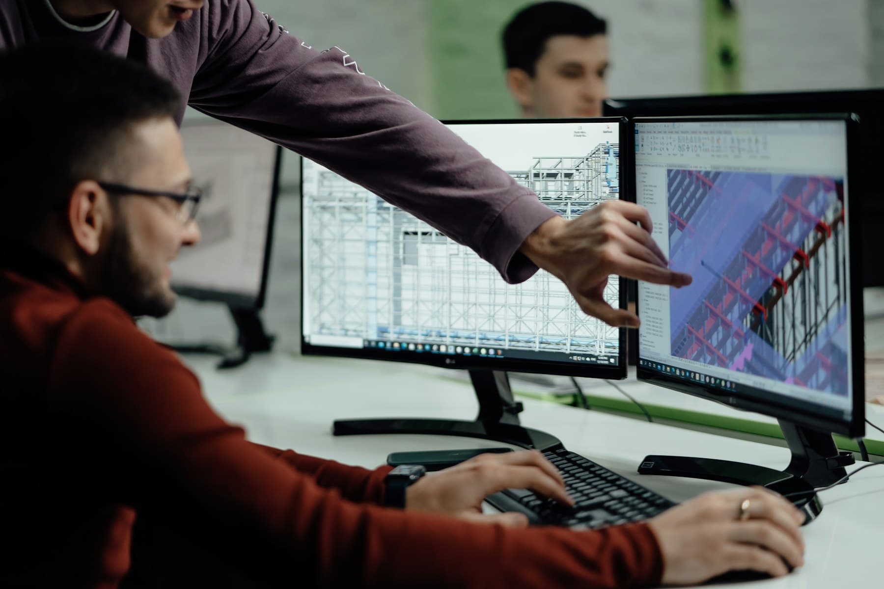
The front end of every project
Design and prototyping is not a separate line of business at BioFlex. It is the first half of every medical, packaging, and biogas job we take on: the same team that models the part draws it for manufacture and, where it helps, prints it first. Rapid prototyping and additive manufacturing are used to put a design in front of the people who will use it, early. Printed fixtures, jigs, and form models let ergonomics, clearance, and fit be checked on the line before any tooling is committed, and short-run printed parts cover the gap while production tooling is being made.
A printed prototype is not always the finished part, and it is not meant to be. Where a printed part is not fit for service, it still de-risks the machined, fabricated, or moulded version that follows, which is the reason to print it at all.
Services
- Concept design and feasibility
- Sketches, layout options, and an honest feasibility view before anyone commits.
- 3D CAD modelling
- SOLIDWORKS models of parts, assemblies, and full equipment layouts.
- 3D printed prototypes
- A physical part to check in the hand, on the bench, or on the line.
- Design-for-manufacture review
- The design checked against how it will actually be cut, formed, or moulded.
- Tolerance, clearance, and fit checks
- Stack-up and motion studies resolved on the model, not on the shop floor.
- Reverse engineering from a sample
- A worn or obsolete part measured, modelled, and re-drawn for manufacture.
- Manufacturing drawings and BOMs
- A release pack a workshop can quote from and build to without a phone call.
- Short-run printed parts
- Bridging parts that keep a line moving while production tooling is made.
How a design gets to a part
The same five operations run on a medical fixture, a thermoform tool, and a biogas dosing rig. What changes is the constraint set, not the sequence.
- OP 10
Brief and constraints
What the part has to do, where it has to fit, who has to handle it, and what it has to comply with. Written down before anything is drawn.
- OP 20
Concept and layout
Two or three credible routes sketched and compared against the constraints, so the option that gets modelled is the one that survived a comparison.
- OP 30
CAD model
The chosen concept modelled in SOLIDWORKS, with clearances, tolerance stack-up, and motion resolved on the model while changing it is still free.
- OP 40
Print and review
A printed part put in front of the operators and engineers who will live with it. Ergonomics, clearance, and fit are judged by hand rather than argued over a screen.
- OP 50
Release for manufacture
Drawings, BOM, and material specification issued once the physical review is closed out, so the machined or fabricated version is built from a design that has already been held.
What we use 3D printing for
Printing is a means of asking a question early, not a product in itself.
- Proving fit before tooling
- A printed form model finds the interference that a rendered assembly hides, while the tool is still a drawing rather than a block of steel.
- Ergonomics on the real line
- Operators judge reach, grip, and handling on a part they can pick up. Fixture geometry changes far more often after this review than before it.
- Bridging a tooling lead time
- Short-run printed parts keep a line running through the weeks between design release and production tooling arriving.
- De-risking the machined version
- Even where a printed part cannot go into service, printing it first means the machined, fabricated, or moulded version is built once rather than twice.
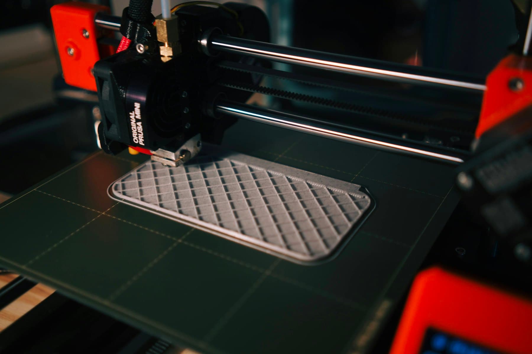
Built layer by layer, infill still open before the top skin closes 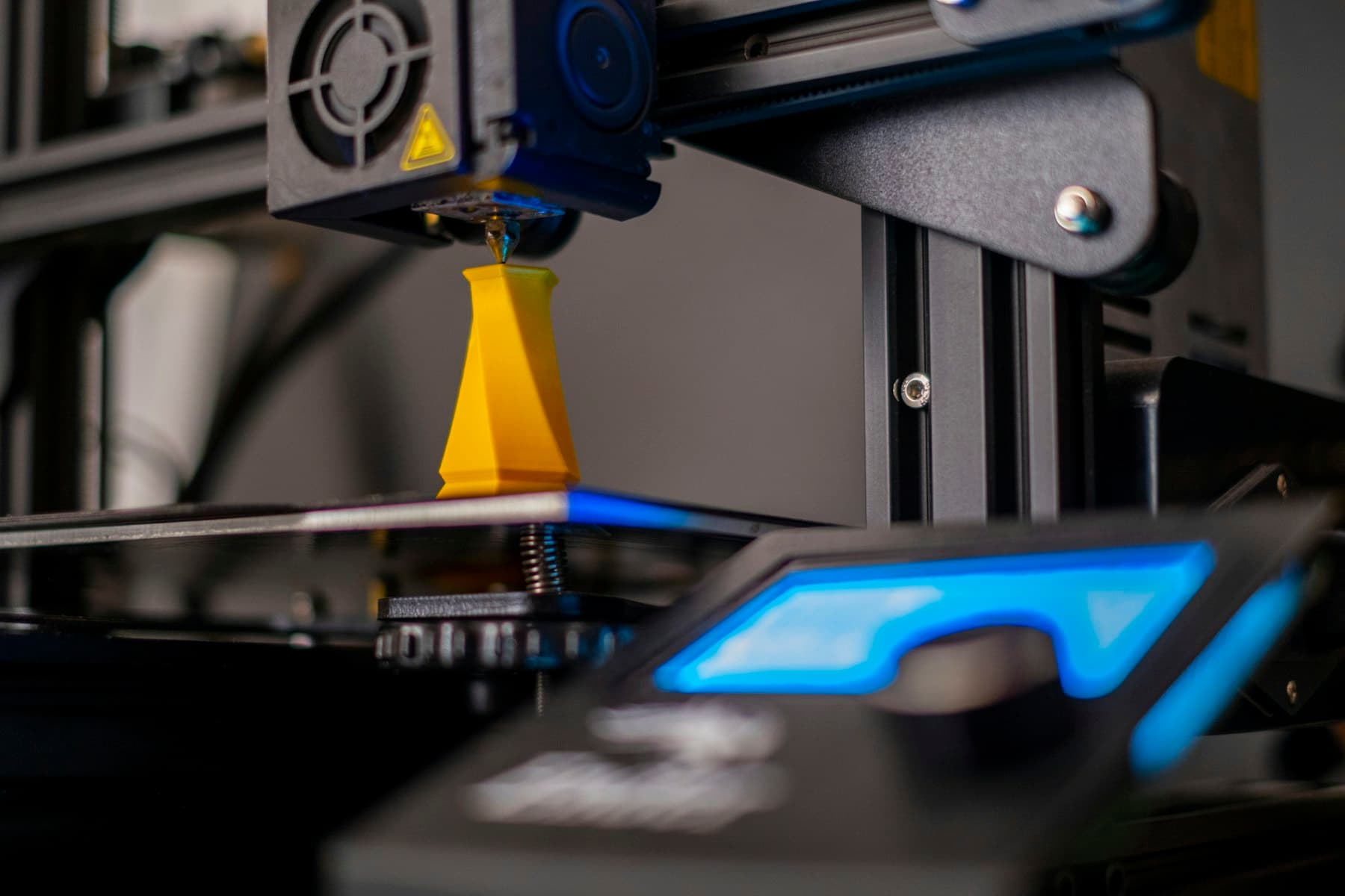
A part mid-build on the bed 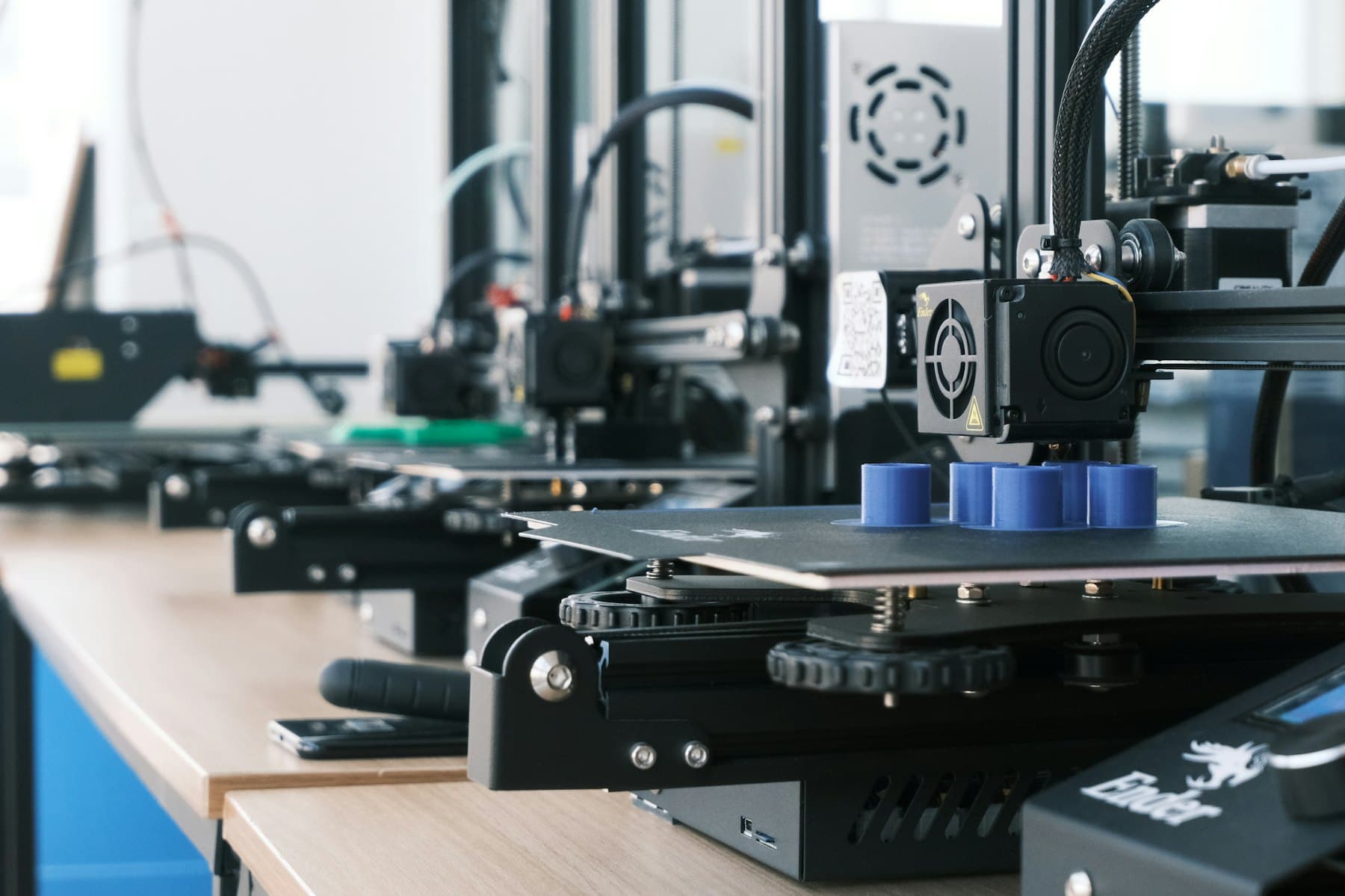
Several iterations printed in parallel
Illustrative. Additive manufacturing in general, not BioFlex project photography.
Why choose us
- One team from sketch to crate
- The engineer who models the part sees it manufactured, so the design is drawn by someone who has to live with it.
- Fast iteration
- A working concept part in weeks rather than quarters, which is what makes it worth iterating at all.
- Design that reaches manufacture
- We do not hand over a model and wish you luck. Drawings, BOM, and tolerances are written to be quoted from and built to.
- Cross-sector experience
- Cleanroom fixturing, thermoform tooling, and farm-scale plant. Constraints from one sector routinely solve a problem in another.
From CAD model to finished tool.
The design pack is the deliverable. This is what one looks like when it reaches the workshop.
Design to finished tool
Fig. 01
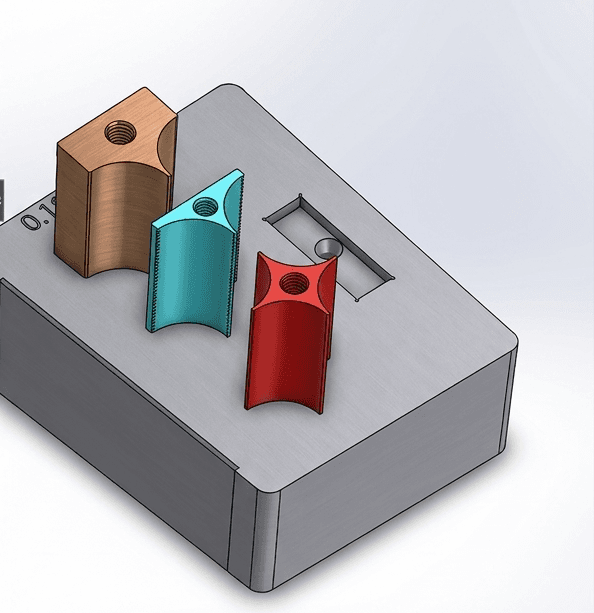
Design
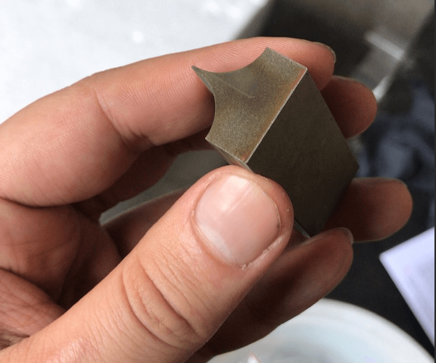
Manufactured
Cutting blade inserts, start to finish
A set of custom cutting blade inserts for a thermoform packaging line, taken from CAD model to installed tool. The blades were CNC-machined from hardened tool steel to the dimensional tolerances and surface finish specified at design stage, and fitted directly to the customer's existing tool block without rework. The design pack was the deliverable that made that possible: the workshop quoted and built from it without a single clarification call. Concept to finished tool in weeks.
SOLIDWORKS · Hardened tool steel · CNC machined · Direct retrofit · Concept to manufacture in weeks
Got an idea that needs drawing?
Send us a sketch, a photo, or a worn part. We'll come back with a scoping outline within 5 business days.